
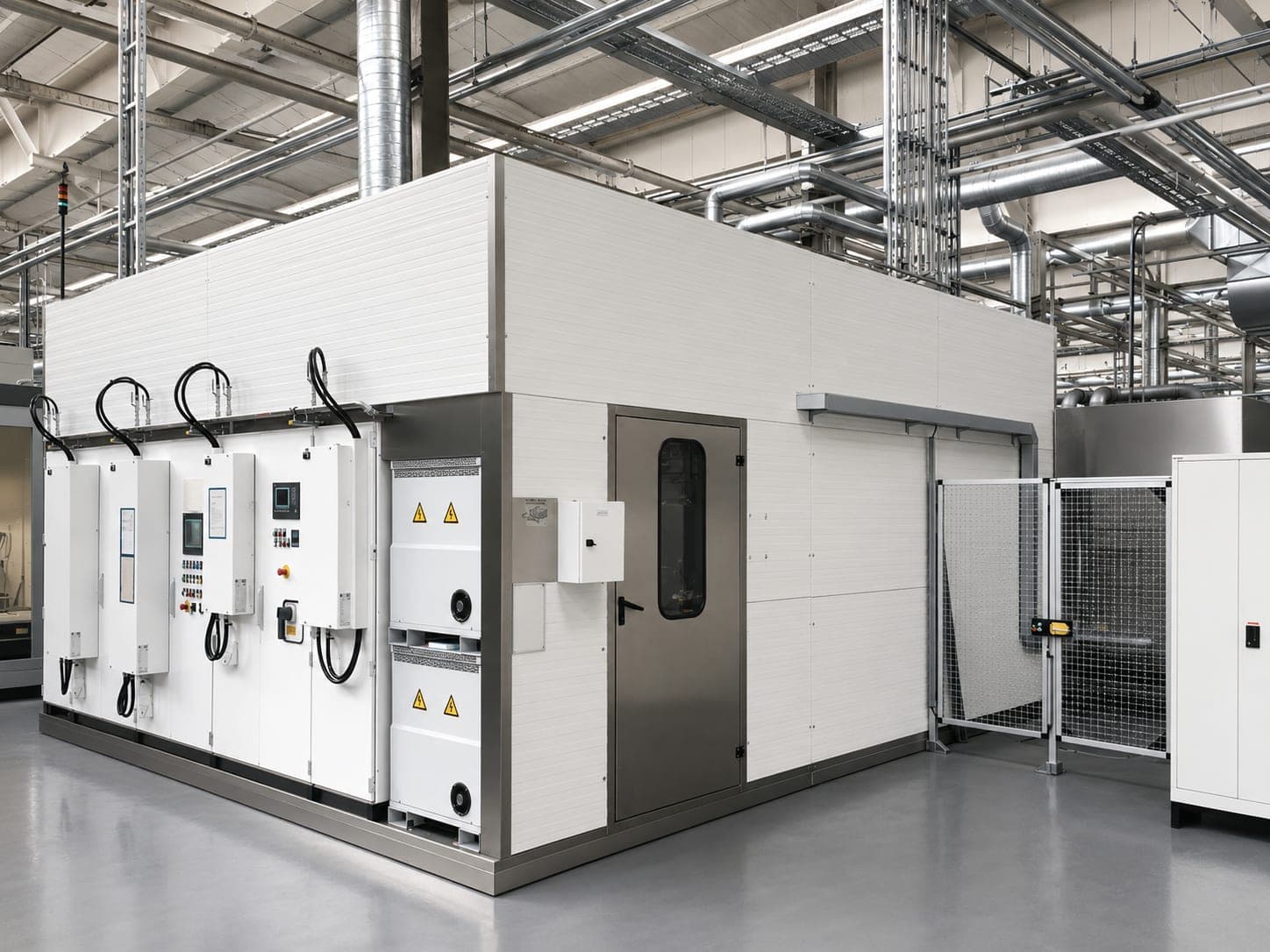
The processing takes longer than the cycle allows.
Dual-Robot Cell
1 · The challenge
It is not the jet that is too slow — it is too many locations
Where this problem occurs
Valve blocks, hydraulic manifolds, gearbox housings, engine blocks, pump housings, turbocharger housings and steering housings — predominantly aluminum die casting. What speaks especially for this concept are components with many spread-out deburring locations in series production: the more locations, the better the work can be divided.
Which burrs are meant
Four of them sit at or in bores — where mechanical tools cannot reach. There is no fixed standard burr type; what counts is the part geometry.
2 · Engineering considerations
First it is checked where the time is actually lost
- 01
Is it the processing?
Then a second robot helps. - 02
Is it the setup and clamping?
Then it does not help — then the auxiliary time has to come out of the cycle, and that is what another concept does.
The second point, just as important: two robots do not automatically mean half the cycle time. How much time is actually gained depends on whether the work on the specific component can be divided sensibly — and whether the robots do not get in each other’s way while doing so. We calculate that before design engineering, not after.
Apart from that, the same factors are assessed as in every deburring task:
The material is rarely the decisive factor. Aluminum, steel, stainless steel, brass, copper, zinc die casting and plastic can all be processed.
3 · The machine concept
The robot cell with two robots
Two robots guide the nozzles — in parallel on the same component or with a divided process, for instance one deburrs while the other handles. Standard is KUKA; we use ABB, FANUC and Yaskawa just as well.
The actual engineering work lies in the division. Which robot takes over which deburring locations, in which order, with which path guidance — and how collisions are ruled out. This division decides the achievable cycle, not the number of robots.
- 01
The nozzles
The tool of the method — standard nozzles as well as our own nozzle geometries when the application requires it. - 02
The water circuit
Closed. Filtration is part of every system; we integrate more extensive water treatment depending on the project. - 03
Safety technology
Safety fences, safety doors, light curtains — according to risk assessment. With two robots in one cell it is more extensive than with one. - 04
The workpiece fixture
Has to give both robots access at the same time — here it is more closely interlocked with the path planning than in a single-robot cell.
Where the concept is extended
- 01
Vision system
- 02
Tool changer
Several nozzle tools, changed during the process. - 03
Barcode and DataMatrix systems
Component identification, program and result per part. - 04
Automatic loading
- 05
Line integration with further systems
- 06
Rotary table
Depending on the project.
4 · The result — and its verification
Two results are verified: residual burr and residual contamination
With short cycles, process monitoring gains weight: it keeps the process within its window instead of checking every part individually.
Where the limits are
When another solution fits
- 01
Single-robot cell
When the cycle time can be reached with one robot as well. The second robot is effort that has to pay off. - 02
Stationary water jet deburring system
When always the same component runs in a fixed clamping position and fixed nozzle systems are enough. - 03
Rotary indexing water jet deburring system (special solution)
When the bottleneck is not the processing time but setup and clamping.
Where the method reaches its limits
When water jet deburring is not the right choice
Defined chamfers or radii are to be produced
The method removes burrs, it does not replace machining.Very firmly adhering or massive burrs are present
They have to be eliminated differently, by design or by manufacturing.The deburring location cannot be reached with any suitable nozzle concept
The method is not economically viable
For example at very small production volumes, or when a simpler deburring method is sufficient.Another method meets the requirements better
Technically or economically.
Scope of supply
More on the system design
Questions and answers
Frequently asked questions about the dual-robot cell
When is a dual-robot cell worthwhile?
How do the two robots work together?
Applications
Components on which this system design is decided
Each case sets out the design factors, the possible system concepts and the methods in detail — here you only find what it is about.
Hydraulic manifold
The channels are drilled, they intersect several times, and at every bore intersection a burr forms.
Valve block
The burr root sits at the bore intersection of two bores — no tool gets there, not because it would be too big, but because no path leads to it.
Components with heavy burrs
Casting flash and metal fines do not sit on one edge but spread out — and later they come loose by themselves.
None of these cases inevitably leads to the dual-robot deburring cell. Which concept it becomes arises from the interplay of the design factors — the machine type is the result of the system design, not its starting point.
Direct contact
Hauptstraße 31
93186 Pettendorf
Pettendorf bei Regensburg
Fax +49 (0) 9409-777 3607