Skip to content
ITR GmbH powered by Zippel
Submit an inquiry
Menu
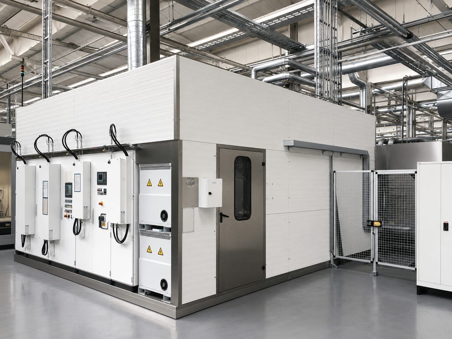
Closed deburring cell in a production hall: a room-high light-colored enclosure, in front of it on the left a row of control cabinets with operating panels, emergency stop and main switches, on the right a safety fence door with a safety switch, above it the media routing of the hall

“We can’t get the burr off.”

High-Precision Water Jet Deburring

Behind that there is rarely a problem with the method — but a burr that sits in a place no tool can reach: at the intersection of two bores, inside a component with branched channels.

1 · The challenge

The burr sits where no tool can reach

Burrs form wherever material has been cut or formed — at bore exits, at bore intersections of cross-drilled and intersecting bores, at milled edges. On the outer surface that is manageable. Inside a component with branched channels it is not: a brush or a milling cutter would have to reach the place where two channels cross.

A burr that stays rarely remains a form deviation. It comes loose later and travels to where the component does its work — into oil and hydraulic channels, to valves, into pumps and gearboxes. A detached burr in the channel is therefore not only a deburring problem but a residual contamination problem — the same question that every parts cleaning system has to answer.

What customers are looking for

  • A reproducibly reliable process

    Deburring by hand works as long as the production volume is small and nobody demands a verification. As soon as both tip over, quality depends on the form of the day.
  • Low residual contamination values

    The detached burr is a cleanliness problem. Deburring and residual contamination belong together.
  • A process that can be automated

    The cycle must not depend on the number of hands.
  • Reliable removal of internal burrs

    Exactly where no mechanical tool can reach.

Which components it is about

Not a list of industries, but a common characteristic: what matters is not the industry the part is installed in, but what it looks like inside — branched channels with cross-drilled holes and bore intersections. What they share is the deburring task, not the shape. Most common are gearbox housings, pump housings, engine blocks and aluminum housings.

Valve blocksHydraulic manifoldsGearbox housingsEngine blocksPump housingsTurbocharger housingsSteering housings

Almost always made of aluminum or aluminum die casting — a material that machines easily and breaks out toughly as it does. The material is nevertheless not a limit; it is the focus because the components are made of aluminum, not because the method would be restricted to it.

Which burrs are meant

Drilling burrsCross-drilled hole burrsIntersecting-bore burrsExit burrsMilling burrsCasting flashMetal fines

Four of the seven sit at or in bores. There is no fixed standard burr type — what counts is the part geometry, not the name of the burr.

2 · When it is the right method

Rarely for a single reason

In most projects several reasons come together — technical cleanliness, process reliability and cost-effectiveness are almost always involved.

This page also tells you the opposite direction. Where the method is not the right choice is set out further down in section 7 — on the same page, not in a footnote. That water jet deburring pays off at high production volumes and not at very small ones is the same consideration from both ends.

3 · One step instead of two

The same jet removes the burr and carries it out of the component

This is not a cross-reference to a second offer, but a property of the method — and that is why it comes before the question of the machine: it changes what is being decided on, one process step or two.
  1. 01Remove the burrThe high-pressure jet detaches the burr at its root.
  2. 02Carry outThe same jet flushes it out of the channel.
  3. 03CleanResidual contamination is removed in the same process, depending on the system design.
  4. 04Dryje nach AuslegungProject-specific, where the component moves on dry.

Depending on the component and the process design, water jet deburring makes it possible to carry out deburring and cleaning in one combined manufacturing step. Where the requirements for technical cleanliness are particularly high, a parts cleaning system can be added downstream. We develop both technologies ourselves and design them for the same component.

4 · Which machine concept fits

First the requirement, then the concept

The selection is made project by project on the basis of several criteria — production volume, cycle time, workpiece size, degree of automation, part geometry, accessibility of the deburring locations, process requirements and the required cleanliness. The budget deliberately sits between the technical criteria, not below them: a system that is technically convincing and does not pay off is not a solution.

The three standard concepts

Stationary deburring machine

Cost-effectiveness with identical parts — identical workpieces, fixed clamping position, fixed nozzle systems are enough.
Single-robot cell

Flexibility — different components, complex geometries, small to medium production runs.

Dual-robot cell

Processing performance — very short cycle times, high production output, parallel processing.

Three concepts, three arguments that do not overlap — which is exactly why the choice is rarely clear-cut. With us the robot solution is the standard; we design without a robot when a fixed clamping position and cost-effectiveness speak for it. That is a reasoned decision, not a budget variant.
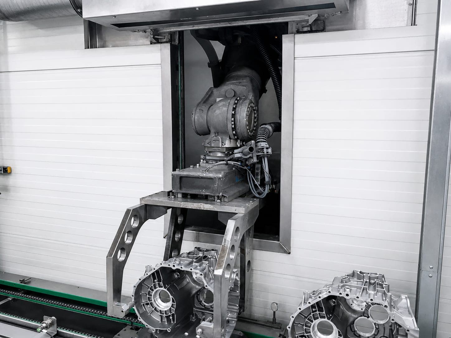
Exit of a deburring cell: an articulated robot guides a component outward through the open lock, on the conveyor belt in front of it stand two cast-aluminum gearbox housings
The robot guides the component out of the cell through the lock. Whether a part is moved like this or stays firmly clamped is one of the factors the concept follows from — it is never decided on a single one.
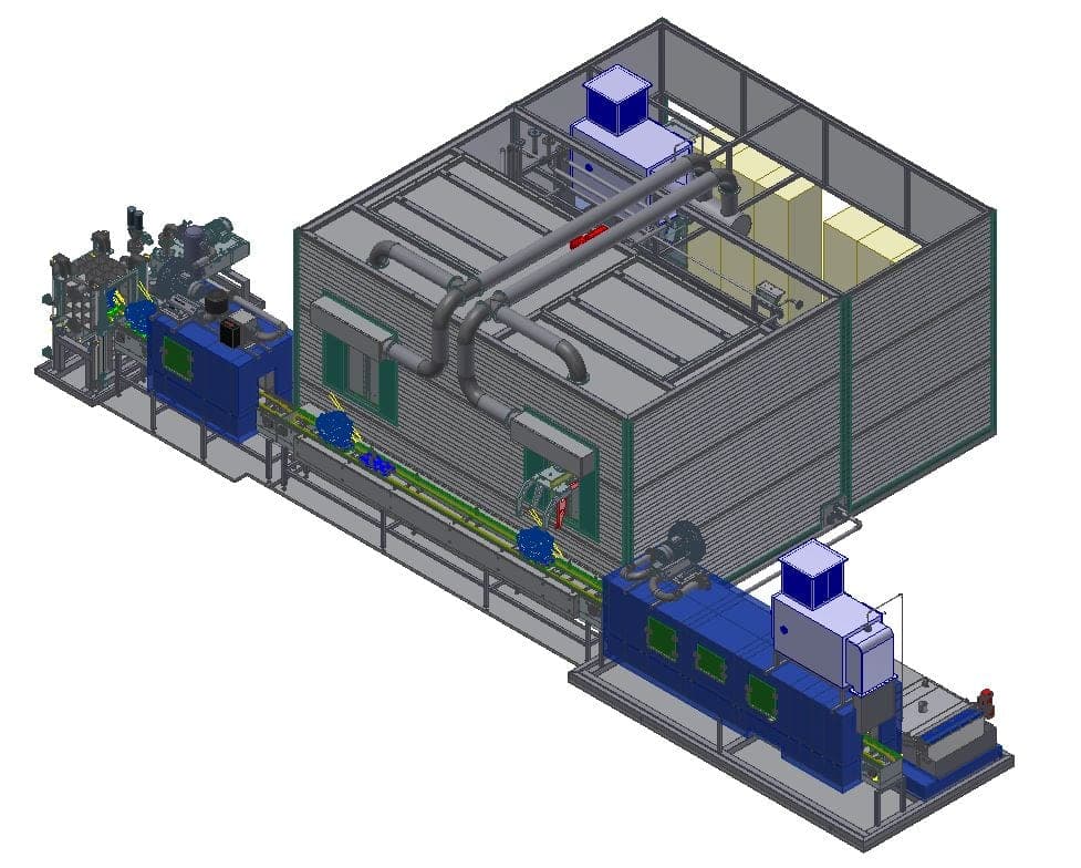
CAD overall view of a water jet deburring system: on the right the enclosed processing cell, in front of it on the left the high-pressure and media technology on its own base frame, in between the material flow and conveying running through
A deburring system consists of more than the cell: high-pressure and media technology stand on their own base frame, the material flow and conveying runs straight through. How each of these is designed follows from the eight factors below.

What we design project-specifically

Once the concept is set, eight factors determine the system: part geometry, material, burr root, accessibility of the deburring locations, cycle time, residual contamination requirement, workpiece fixture and degree of automation. Burr root and accessibility are the two on which the system design turns: the task is not “the burr”, but where it starts, how firmly it sits — and whether a jet can reach it.

Depending on the project, the pressure range lies roughly between 300 and 1,500 bar; unnecessarily high pressure is avoided. The process medium is designed as well — as a rule water, depending on the requirement with corrosion protection, cleaner or additives. All other values come about in the quotation: there are no data sheets for special-purpose systems.

Stationary deburring machine

Designed for
Identical workpieces, fixed clamping position
The argument
Cost-effectiveness with identical parts
Production run
Identical parts

Single robot

Designed for
Different components, complex geometries
The argument
Flexibility
Production run
Small to medium

Dual robot

Designed for
Very short cycles, high output
The argument
Processing performance
Production run
High, parallel
The deburring method is never selected on the basis of a single characteristic, but always on the basis of the entire process requirement. This selection aid is orientation, not a configurator — the concept is the result of a system design, not an assignment.

5 · Typical applications

Where the burr sits, and what follows from it

Six tasks of the kind that come up every day. It is not the component that decides the concept, but the position of the burr root and what comes after deburring.

What tips the scales in a case is on its own page: the design factors, the possible system concepts and the methods in detail.

Cylinder head

Deburred by hand, every result is a different one — what works on a test part does not carry a production run.

Gearbox housing

The burr sits in the internal channel of the gearbox housing — where no mechanical tool can reach.

Hydraulic manifold

The channels are drilled, they intersect several times, and at every bore intersection a burr forms.

Valve block

The burr root sits at the bore intersection of two bores — no tool gets there, not because it would be too big, but because no path leads to it.

Components with heavy burrs

Casting flash and metal fines do not sit on one edge but spread out — and later they come loose by themselves.

High technical cleanliness

When deburring a component with a verification requirement, the burr must not only be gone — it must be demonstrable that it is gone.

These six cases, too, are orientation, not a key. Depending on part size, production volume and cycle time, the same burr type can call for a different machine concept — the selection is never made on the basis of a single characteristic.

6 · Special solution

Rotary indexing — when the bottleneck is not the processing but the setup

We realize rotary indexing deburring cells for water jet deburring on a project-specific basis. They are not among the three standard concepts because their argument is a different one.

With the rotary indexing principle, loading and unloading run in parallel with processing — the auxiliary time drops out of the cycle. That pays off when setup and clamping time are considerable in relation to the processing time.

Rotary indexing water jet deburring system

7 · Where the method reaches its limits

Water jet deburring is not automatically the best solution

Water jet deburring is not the optimal choice if one of these prerequisites applies:
  • Defined chamfers or radii are required

    The method removes burrs, it does not replace machining — the jet does not shape the edge.
  • Very firmly adhering or massive burrs

    They have to be eliminated differently, by design or by manufacturing.
  • The deburring location cannot be reached with any nozzle concept

    Whether it can be reached is decided by the geometry, not by the size of the burr.
  • It is not economically viable

    For example at very small production volumes, or when a simpler deburring method is sufficient.
  • Another method meets the requirements better

    Technically or economically.

The first and the third point are the two worth checking before an inquiry. The material is rarely the decisive factor here: aluminum, steel, stainless steel, brass, copper, zinc die casting and plastic can all be processed. Tell us early what you have in mind. If another method is the better fit, we will say so.

8 · What comes next

Deburring never stands alone

Deburring is one step in a process chain. What happens before and after it — cleaning, drying, inspection, automation — belongs in the same system design.

9 · Where our deburring systems are installed

The industry follows the component

Gearbox, pump and engine housings and valve blocks are produced in foundry and die casting and are installed in automotive and machinery manufacturing. Wherever these parts are made, burrs form in internal channels — and that is where the method is found.

Already realized

AutomotiveFoundryDie castingMachinery manufacturingAerospace

What remains decisive is the component, not the economic sector. The method is not tied to any industry: wherever a component is branched inside and the burr cannot be reached mechanically, we design for it — regardless of the industry it is installed in.

10 · Scope of supply and verification

Two results are verified: residual burr and residual contamination

Is the burr gone — and is the part clean? Both verifications come from a single source. Which inspection methods are used in the individual case is set out on the pages of the machine concepts.

The scope of supply is defined project-specifically. Depending on the requirement, it comprises the water jet deburring system, filtration, water treatment, drying, automation, documentation, CE conformity and training. Drying is not included as standard — where the component has to move on dry, it is integrated project-specifically.

Questions and answers

Frequently asked questions about water jet deburring

What is water jet deburring?

A method that removes burrs with a precisely guided high-pressure water jet — above all where no tool can reach. The burr sits at the intersection of two bores. A brush or a milling cutter would have to reach the place where two channels cross. That is not possible. Exactly this gap is what the jet closes.

Why is a burr in the component a problem at all?

A burr that stays rarely remains a form deviation. It comes loose later and travels to where the component does its work — into oil and hydraulic channels, to valves, into pumps and gearboxes. A detached burr in the channel is therefore not only a deburring problem but a residual contamination problem: the same question that every parts cleaning system has to answer.

Which burrs can be removed with a water jet?

Drilling burrs, cross-drilled hole burrs, intersecting-bore burrs, exit burrs, milling burrs, casting flash and metal fines. Four of the seven sit at or in bores — exactly where no tool can reach. There is no fixed standard burr type: what counts is the part geometry, not the name of the burr.

Which components is it typically about?

Valve blocks, hydraulic manifolds, gearbox housings, engine blocks, pump housings, turbocharger housings and steering housings. Most common are gearbox housings, pump housings, engine blocks and aluminum housings. All of them share the same characteristic: internal channels with cross-drilled holes and bore intersections. What they share is the deburring task, not the shape — it is not a list of industries and not a statement about the design.

Does water jet deburring only work with aluminum?

No. Aluminum is the focus because the typical components — gearbox, pump and engine housings, valve blocks — are predominantly made of aluminum or aluminum die casting. The method is not restricted to it: steel, stainless steel, brass, copper, zinc die casting and plastic can be processed just as well. Whether the method fits is decided by part geometry, burr root, accessibility and the process goal — rarely by the material.

When is water jet deburring better than mechanical deburring?

When the burr sits inside. On the outer surface, mechanical deburring is manageable — inside a component with branched channels it is not. Then there is cost-effectiveness: deburring by hand works as long as the production volume is small and nobody demands a verification. As soon as both tip over, quality depends on the form of the day and the cycle on the number of hands.

Can deburring and cleaning be done in one step?

Yes — depending on the component and the process design. The same jet that removes the burr also carries it out of the component; otherwise the detached burr would remain in the channel. Where the requirements for technical cleanliness are particularly high, a parts cleaning system can be added downstream. That changes what is being decided on: one process step instead of two.

When is water jet deburring not the right method?

Water jet deburring is not the optimal solution when defined chamfers or radii are to be produced, when very firmly adhering or massive burrs are present, when the deburring location cannot be reached with any suitable nozzle concept, when the method is not economically viable — for example at very small production volumes — or when another method meets the requirements better. The first and the third point are the two worth checking before an inquiry.

Does water jet deburring produce defined chamfers?

No. The method removes burrs, it does not replace machining. Anyone who has a defined chamfer in the requirements specification needs a different method: the jet removes the burr, it does not shape the edge.

Which system concept fits my component?

That cannot be assigned in advance. There is no generally valid standard system design, and the selection is never made on the basis of a single characteristic. Burr root and accessibility are the two factors on which the system design turns: the task is not “the burr”, but where it starts, how firmly it sits — and whether a jet can reach it.

Which machine concepts are there?

Three standard concepts, each with its own argument: the stationary deburring machine for cost-effectiveness with identical parts in a fixed clamping position, the single-robot cell for flexibility with changing components and complex geometries, and the dual-robot cell for processing performance at very short cycle times. Three arguments that do not overlap — which is why the choice is rarely clear-cut.

When is a robot cell worthwhile?

When flexibility is needed: different components, complex geometries, small to medium production runs. With us the robot solution is the standard. We design without a robot when a fixed clamping position and cost-effectiveness speak for it — that is a reasoned decision and not a budget variant.

What distinguishes the single-robot cell from the dual-robot cell?

The argument, not the number. The single robot stands for flexibility — different components, complex geometries, small to medium production runs. The dual robot stands for processing performance: very short cycle times, high production output, parallel processing. Anyone who needs both gets a system design, not an assignment.

Which pressures are used in water jet deburring?

Depending on the project, we realize systems in the range of roughly 300 to 1,500 bar. What your component needs is decided by the material, the burr geometry, the burr root, the part geometry and the desired result. We avoid unnecessarily high pressure — it damages components without removing the burr any better. More pressure is not more quality.

What is used — only water?

As a rule we work with water; depending on the requirement, corrosion protection, cleaner or additives are added. Which of these makes sense follows from the material, the downstream process and the required cleanliness. The choice of process medium is therefore part of the process design, not a property of the system.

Is drying included in the scope of supply?

Not as standard. The scope of supply is defined project-specifically and can comprise the water jet deburring system, filtration, water treatment, drying, automation, documentation, CE conformity and training. Where the component has to move on dry, we integrate drying project-specifically — it is part of the system design, not a self-evident component.

How can I automate my manual deburring?

Through the combination of robot, water jet deburring and automated workpiece handling. The trigger is almost always the same: deburring by hand works as long as the production volume is small and nobody demands a verification. Whether it pays off, we tell you beforehand — at very small production volumes, water jet deburring is not economically viable, and then we say so.

Which industries do you build deburring systems for?

Already realized: automotive, foundry, die casting, machinery manufacturing and aerospace. That is no coincidence of sales, but the consequence of the components: gearbox, pump and engine housings and valve blocks are produced in foundry and die casting and are installed in automotive and machinery manufacturing. What remains decisive is the component, not the economic sector.

Direct contact

AddressITR GmbH powered by Zippel
Hauptstraße 31
93186 Pettendorf
Pettendorf bei Regensburg
Phone+49 (0) 9409-777 3598
Fax +49 (0) 9409-777 3607

Technically responsible for this page: Kersten JohnSenior Consultant Technical Cleanliness