The robot is rarely the problem. What holds, guides and controls it is.
Robotics

1 · The challenge
A robot that reliably executes the wrong motion solves no task
What is it gripped with?
Without damaging the component and without losing it — with sensitive, warm or uneven parts, that is the hardest question of the whole cell.How does the system detect the position?
Is the part there at all, and does it lie the way the grip expects it to?Who coordinates motion and control?
Robot motion and system control are two programs. They have to fit together — even in the event of a fault.What happens with the next component?
If the next part looks different, this is where it is decided whether the cell keeps up or has to be rebuilt.
2 · Engineering considerations
First the component, then the grip, then the robot
Order of the system design
- 01ComponentGeometry, weight, surface and position are recorded.
- 02GripFrom that follows how the part is picked up safely.
- 03RobotOnly now are payload, reach and number of axes fixed.
- 04CellControl system, safety technology and surroundings follow the grip.
Machine vision is examined, not presupposed
It is not standard equipment on every system. It is used when it is technically required or when you want it. Where the part position can be defined mechanically, that is the simpler and more robust solution — a camera that detects a position which is fixed anyway costs money and can fail.
Programming is two disciplines, not one
PLC programming controls the system, robot programming controls the motion. We do both in our own company, project-specifically. That is the difference from an integration in which two suppliers wait for each other as soon as something changes at one point.
There is no fixed rule “task X → cell Y”. Which solution is the right one is decided by component, production volume, cycle time, range of parts, workpiece fixture, degree of automation and cost-effectiveness together. We calculate every system accordingly, not from a catalog.
3 · The solution concept
What comes together in the cell
Robot integration
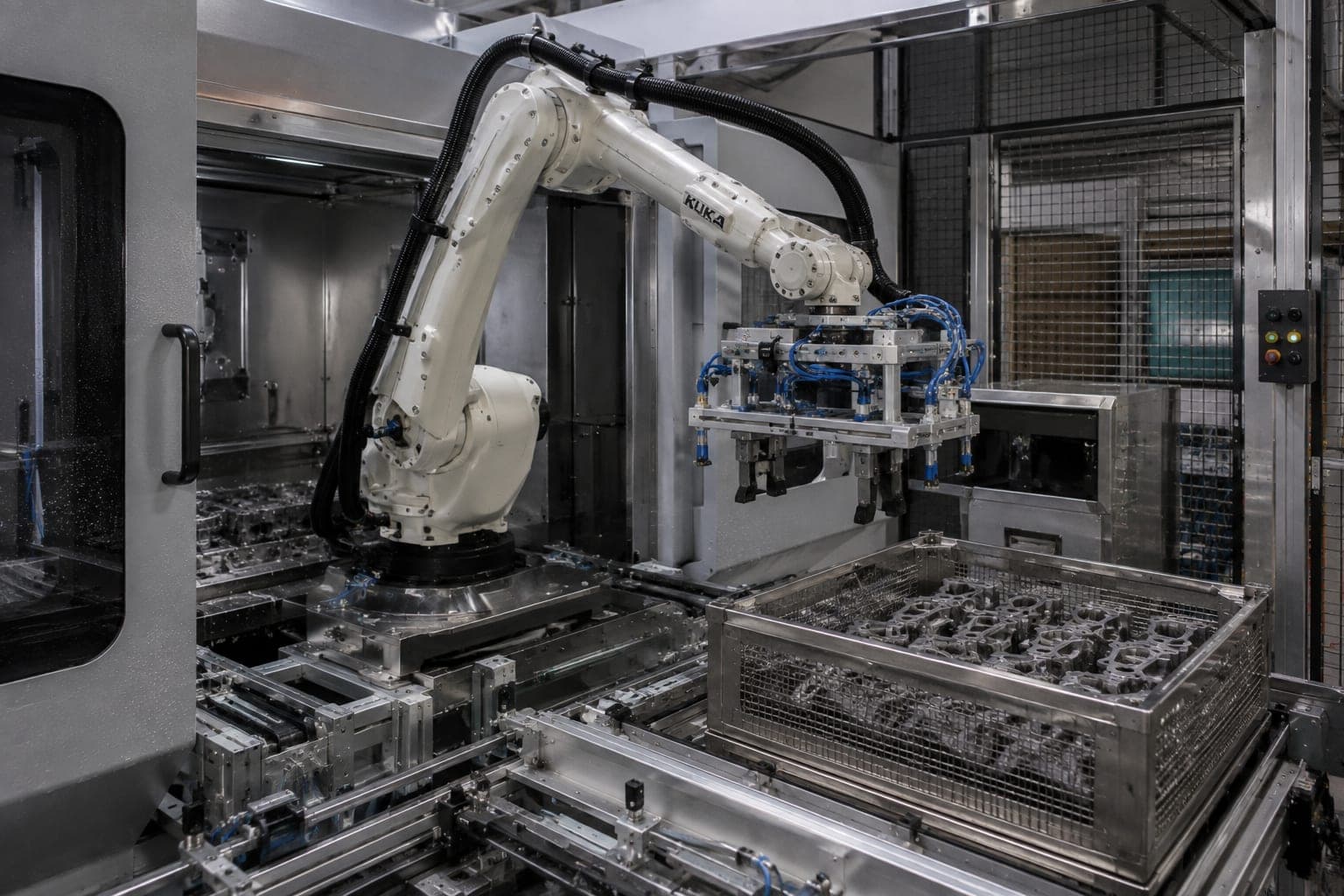
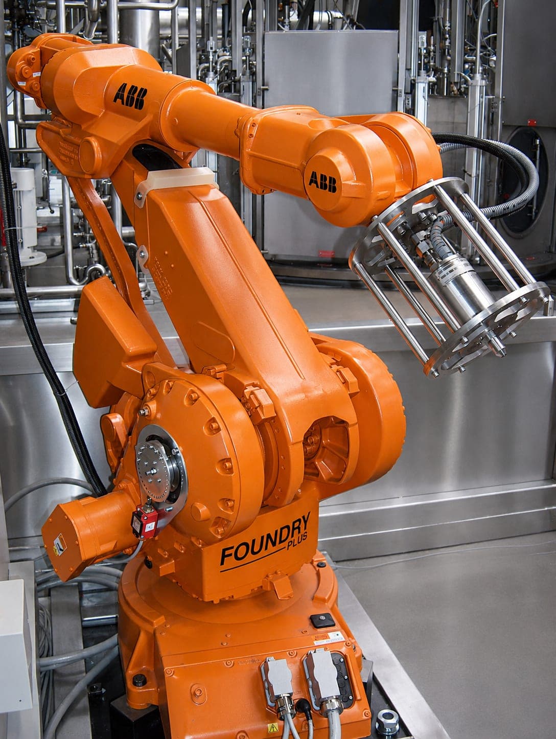
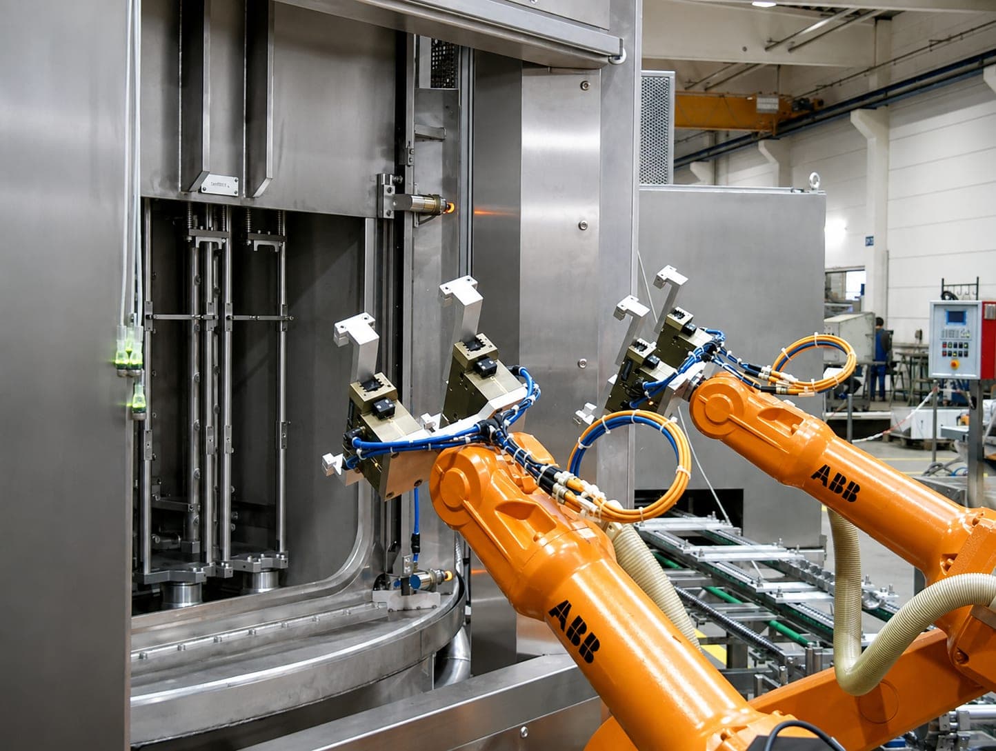
Our standard is KUKA. At the customer’s request we use other robot manufacturers — including ABB, FANUC and Yaskawa. If your factory standard specifies a make, we follow it. The standard is our recommendation, not a prerequisite.
Gripper technology
Here we are deliberately flexible. Depending on the project, standard grippers are used, we design customer-specific grippers, or we develop them together with specialized partners. There is no tie to a particular manufacturer: what counts is the grip that fits the component — not the origin of the gripper.
Control system and programming
Our standard is Siemens PLC; HMI and control cabinet components are predominantly Siemens. PLC programming is carried out project-specifically by us, as is robot programming. We build the control cabinet ourselves.
Machine vision
For detecting the position of the component or for checking the result — when it is technically required or wanted. Not standard equipment.
Safety technology
Safety fences, safety doors, light curtains and further measures — designed according to risk assessment, not from a catalog.
4 · The result
One contact for mechanics, control system and motion
For you, that means: changes to the system do not run through three suppliers. Whoever designed the mechanics also programmed the control system — and is the same person you call in two years.
Cross-section
Where else robotics is found with us
Loading and unloading of parts cleaning systems is robot-supported — with the rotary indexing cleaning system, that is the defining characteristic of the configuration. And water jet deburring is predominantly robot technology with us: there, the robot guides the nozzle.
Scope of supply
Vertical integration and digital system lifecycle
Questions and answers
Frequently asked questions about robotics and control systems
Which control system is used?
How is a robot cell programmed?
Applications
Components on which the automation is decided
Each case sets out the design factors, the possible system concepts and the methods in detail — here you only find what it is about.
Cylinder head
The spray jet hits what it sees — and what it does not see only becomes visible in the residual contamination verification.
Aluminum die-cast part
Contamination on an aluminum die-cast part adheres differently than a cooling lubricant — and what has to come out of the cavity sits in a geometry that was built for exactly that: to be inaccessible.
Defined part temperature
The component is clean and dry — and still not ready for handover: a part that is too warm is of no use for a leak test.
Large and heavy parts
Size and weight are not a surcharge on an existing system design: they act on system dimensions, payload, workpiece fixture and loading at the same time.
Also with a robot solution as a possible concept: Multiple part variants
None of these cases inevitably leads to a robot solution. Which concept it becomes arises from the interplay of the design factors — the machine type is the result of the system design, not its starting point.
Direct contact
Hauptstraße 31
93186 Pettendorf
Pettendorf bei Regensburg
Fax +49 (0) 9409-777 3607